OpenGL follows a “diamond exit” rule for line rasterizing. The pixel area is considered with an internal diamond and the line must leave it to be drawn. This helps with smooth transitions between line segments.
The second or follow up is that the last pixel is not drawn. It never leaves the diamond.
Drawing lots of short lines can all stay inside the pixel area and never be drawn. Drawing line strips are treated as a longer, continuous line and the pieces do exit the diamonds.
Another “read the specifications carefully” note is that line width other than one is not guaranteed to be implemented, and the implementation details have similar subtle details like handling of line end caps and miters at joints. For thick lines your own quads may be better, as well as shapes for end caps and miters.
Enjoy the learning.
I did read the specs and effectively noticed this, but that left me with more questions than answers…
Aybe One said: But then GL_LINESTRIP thickness isn't even, unless one goes 4K it's noticeable:
You could render at higher resolution and sample it down for higher quality. You could keep resolution but use TAA. Double resolution + MSAA + downsampling should give high quality.
Or you could use a compute shader to do whatever you want, including analytical anti aliasing.
Or you could try a library like OpenVG which would care about it all, but idk about widespread GPU support.
Aybe One said: Bresenham
Afaik Bresenham does not support subpixel accuracy. Use DDA instead.
Yes, #1 would likely tackle the problem, #2/#3 are out of reach for me.
I too tried DDA… until I realized I needed neither of these, just vertical lines.
JoeJ said:
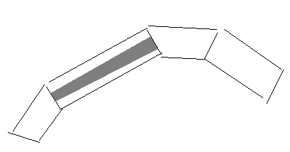
Assuming you don't need a depth test, you could do the AA cheaply with alpha blending. But then you need to generate a ‘thick’ mesh, turning each line segment into a quad (which is tricky on high curvature due to self intersections):
I've drawn the alpha texture in one quad. Grey means opaque and white means transparent. I guess a width of 2 or 3 texels would give a good compromise between smoothness and sharpness.
Forgot to mention, basically I want aliased lines 😁.
dpadam450 said:
I ran a small test on my PC. So understand that if glLineWidth = 1.0, then you have a line that could be intersecting up to two pixels to the left and right. Imagine a vertical line between pixel 0 and pixel 1, and the lines x value is 0.5, that means the width of rasterization is 2, while the line is 1 pixel thick.
Anyway I looked into this a bit and determined that glLineWidth = .75 or so may help get closer to what you want. I made a program where you press a key (pause for 1 second so you can see exactly one iteration). Each iteration subtract 0.05 value from line width and see how it looks. Not certain you will still be happy. Anything under .7 for me starts to drop pixels because the line isn't thick enough at certain locations to be encroaching close enough to a pixel center.
If I was using vanilla OpenGL, I would have tried this, but Unity's is the most basic GL you can think of.
dpadam450 said:
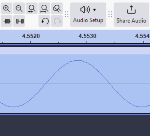
Also, this is how Audacity looks. This is the most zoomed in you can get. This looks pretty weird with many dimples.
Looked at it before, yes it's bad, Audacity is quite inaccurate/simplistic, e.g. not even a zoom factor label…
Following your suggestions, I took another look at the shader approach but well, couldn't get it up. Either it trims too much or not enough, it's miles behind the code I posted… Beside that trailing error effect (which is barely noticeable), I don't think I can get any better.
Funny how when one has something working but don't like it much, one would consider scrapping it. 🤣
Fallback plan would be thick 2 pixels lines with MSAA which looks solid but, thing is, with 1 pixel aliased lines, I don't get that anisotropy effect while scrolling, whereas with line strip + optional MSAA it's there.
Anyway, thanks for pushing me in the right direction! 😁
Looks like the diamond exit rendering again. It shows up in many rendering scenarios, so it is worth understanding in depth.
Just because you sent something to render there doesn't necessarily mean a pixel gets filled. Pixels represent an area and the renderer looks at if enough area was covered to justify filling the pixel.
Yes, I did but got a headache doing so, kept it in my bookmarks and plan to read it again!
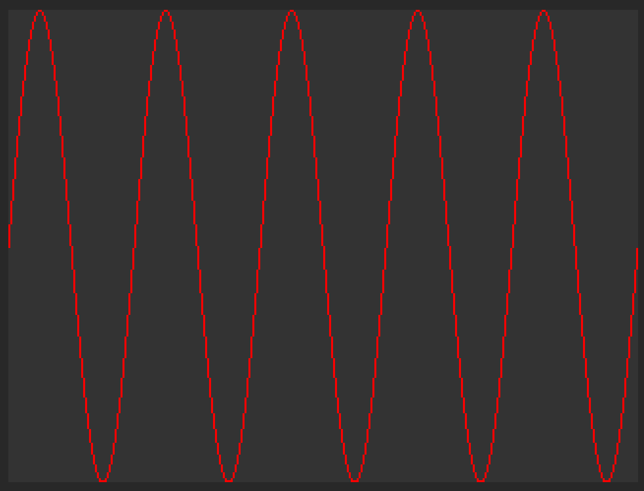
Yes! Your idea led me to try compute shader and that worked! 🥳
No more need to fiddle with half pixels and so on, just ints:
#pragma kernel CSMain

struct Line
{
	int X1;
	int Y1;
	int Y2;
	float4 Color;
};

float4 Clear;

StructuredBuffer<Line> Lines;

int LinesCount;

RWTexture2D<float4> Result;

[numthreads(8, 8, 1)]
void CSMain(uint3 id : SV_DispatchThreadID)
{
	int2 xy = id.xy;

	Result[xy] = Clear;

	for (int i = 0; i < LinesCount; i++)
	{
		const Line data = Lines[i];

		if (xy.x == data.X1)
		{
			const int y1 = data.Y1;
			const int y2 = data.Y2;

			if (xy.y >= min(y1, y2) && xy.y <= max(y1, y2))
			{
				Result[xy] = data.Color;
			}
		}
	}
}
Feeding the shader is now much simpler:
for (var x = 0; x < width; x++)
{
    var peak = peaks[(channel.PeaksIndex + x + 0) % channel.PeaksCount];
    var next = peaks[(channel.PeaksIndex + x + 1) % channel.PeaksCount];

    var min = peak.Min;
    var max = peak.Max;

    if (max < next.Min)
    {
        max = next.Min;
    }

    if (min > next.Max)
    {
        min = next.Max;
    }

    var y1 = (int)((0.5f + 0.5f * min) * height);
    var y2 = (int)((0.5f + 0.5f * max) * height);

    if (y2 - y1 > Adjust)
    {
        y2--;
    }

    Lines[x] = new Line
    {
        X1 = x,
        Y1 = y1,
        Y2 = y2,
        Color = Color.red
    };
}
Still need to tune that adjustment hack to get the tiny peaks right but it's already very good! 🙂
I also stumbled upon https://twistedwave.com/, code has cryptic logic but the rendering is excellent.

.gif)