Welcome to this first article of this ray tracing series. We will be building a fully functional ray tracer, covering multiple rendering techniques, as well as learning all the theory behind them. In this part we will whip up a basic ray tracer and cover the minimum needed to make it work. Going over all of it in detail would be too much for a single article, therefore I've separated the workload into two articles, the first one introductory and meant to get the reader familiar with the terminology and concepts, and the second going through all of the math in depth and formalizing all that was covered in the first article.
The First Step
Vectors and Matrices
The very first step in implementing any ray tracer is obtaining a vector math library. Linear algebra is the cornerstone of most things graphics, so it is vital to have a solid grasp and (ideally) implementation of it. This series will assume you are at least familiar with three-dimensional vector, matrix math, and coordinate systems. Knowledge of projection matrices is not required, but doesn't hurt. A good knowledge of calculus up to integrals is also important. Coding up your own library doesn't take too long, is sure to at least meet your needs, and lets you brush up on your math, therefore I recommend doing so if you are writing a ray tracer from scratch following this series.
Otherwise, there are dozens of widely used libraries that you can use - just be sure not to use a general purpose linear algebra library that can handle arbitrary dimensions, as those are not very well suited to computer graphics work (we will need exactly three dimensions, no more, no less). You may or may not choose to make a distinction between points and vectors. It is not strictly required to do so (you can get by perfectly well representing points as vectors), however, differentiating them gains you some semantic expressiveness and also adds an additional layer of type checking, as you will no longer be able to add points to points, multiply a point by a scalar, or other operations that do not make sense mathematically.
The coordinate system used in this series is left-handed, with the x-axis pointing right, y-axis pointing up, and z-axis pointing forwards.
Projection in Ray Tracing
Before we can render anything at all, we need a way to "project" a three-dimensional environment onto a two-dimensional plane that we can visualize. When using graphics engines like OpenGL or DirectX, this is done by using a view matrix, which rotates and translates the world such that the camera appears to be at the origin and facing forward (which simplifies the projection math) and then applying a projection matrix to project points onto a 2D plane in front of the camera, according to a projection technique, for instance, perspective or orthographic.
In ray tracing, things are slightly different. Instead of projecting points against a plane, we instead fire rays from the camera's location along the view direction, the distribution of the rays defining the type of projection we get, and check which rays hit an obstacle. Each ray intersects a plane (the view plane in the diagram below) and the location of the intersection defines which "pixel" the ray belongs to. Which, mathematically, is essentially the same thing, just done differently.
The view plane doesn't have to be a plane. It is a continuous surface through which camera rays are fired, for instance, for a fisheye projection, the view "plane" would be the surface of a spheroid surrounding the camera. But since it is a plane for projections which conserve straight lines, it is typical to think of it as a plane.
Doing this for every pixel in the view plane, we can thus "see" the world from an arbitrary position, at an arbitrary orientation, using an arbitrary projection model. We can increase the resolution of the camera by firing rays at closer intervals (which means more pixels). In practice, we still use a view matrix, by first assuming the camera is facing forward at the origin, firing the rays as needed, and then multiplying each ray with the camera's view matrix (thus, the rays start in camera space, and are multiplied with the view matrix to end up in world space) however we no longer need a projection matrix - the projection is "built into" the way we fire these rays. As you can probably guess, firing them in the way illustrated by the diagram results in a perspective projection. If we instead fired them each parallel to the view plane, we'd get an orthographic projection. If we fired them in a spherical fashion all around the camera, this would result in a fisheye projection.
You can think of the view plane as a "window" into the world through which the observer behind it can look.
Mathematically, we can describe our camera as a mapping between \(\mathbb{R}^2\) (points on the two-dimensional view plane) and \((\mathbb{R}^3, \mathbb{R}^3)\) (a ray, made up of an origin and a direction - we will refer to such rays as camera rays from now on). Therefore, a typical camera implementation has a signature similar to this: Ray GetCameraRay(float u, float v); But wait, what are \(u\) and \(v\)? We know that they represent a 2D point on the view plane, but how should we calculate them? Recall that each point represents (or at least intersects) a given pixel on the view plane. But we'd also like our view plane to have the same dimensions, regardless of the resolution at which we are rendering (remember: when we increase the resolution, we want to see better, not more, which means reducing the distance between individual pixels). Therefore, we should use resolution-independent coordinates, which are calculated as: \[(u, v) = \left ( \frac{w}{h} \left [ \frac{2x}{w} - 1 \right ], \frac{2y}{h} - 1 \right )\] Where \(x\) and \(y\) are screen-space coordinates (i.e. between zero and the resolution width/height minus 1) and \(w\), \(h\) are the width and height of the image in pixels.
This is very similar conceptually to clip space in OpenGL/DirectX, but not quite the same thing.
The equation makes sense, we're scaling \(x\) and \(y\) so that they fall into a fixed range no matter the resolution. But why is there a \(\frac{w}{h}\) factor on one of the coordinates? It has to do with aspect ratio, and ensuring the view plane has the same aspect ratio as the image we are rendering into. If this term wasn't there, the view plane would remain square no matter the aspect ratio of the image, which would lead to distortion.
It is important to note that \(x\) and \(y\) don't have to be integers. You can very well have a non-integer screen-space coordinate (as long as it is within the required range) which will produce a camera ray that intersects a point located somewhere between two pixels on the view plane. This will be important in later parts when discussing anti-aliasing.
This assumes that the y-coordinate in screen space points upwards. This is historically not the case because of the top-left/bottom-right convention, so your image might appear flipped upside down, simply reversing the height will ensure the two coordinate systems agree.
Finally, now that we know how to actually use the camera, we need to implement it. This means calculating the camera ray, knowing a point on the view plane. As we said before, the direction and position of the camera are irrelevant, we can just assume the camera is looking "forward" (say, along the z-axis) and located at the origin, and just multiply the resulting ray with the camera's view matrix, and we're done. Let's implement a perspective camera.
The "view matrix" here transforms rays from camera space into world space. This is the opposite of what OpenGL/DirectX do, as they tend to transform vertices from world space into camera space instead.
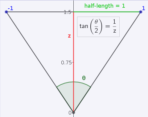
The origin of the camera ray is clearly the same as the position of the camera, this is true for perspective projection at least, so the ray starts at the origin in camera space. What about the direction of the ray (still in camera space)? Let's assume our view plane is at distance 1 from the camera along the z-axis. Then, the vector from the origin to the point on the view plane is just \(u, v, 1\). But the choice of placing the view plane at a distance of 1 unit seems rather arbitrary. Recall that the view plane behaves somewhat like a window conceptually. So, if it were closer to us, we would have a larger field of view. If it were further away, our field of view would be reduced. In fact, the distance of the view plane is related to the field of view of the camera, by the following relation: \[z = \frac{1}{\tan{\left ( \frac{\theta}{2} \right )}}\] This can be seen by drawing a diagram and looking at the tangent of half the field of view:
As the direction is going to be normalized, you can avoid the division by noting that normalize([u, v, 1/x]) = normalize([ux, vx, 1]), but since you can precompute that factor it does not really matter. This is a good general-purpose trick to keep in mind however.
We could then implement our camera algorithm as follows:
Ray GetCameraRay(float u, float v)
{
  float fovFactor = 1 / tan(fov / 2); // this could be precomputed

  Vector origin = new Vector(0, 0, 0);
  Vector direction = Normalize(new Vector(u, v, fovFactor));
  Ray ray = new Ray(origin, direction);

  return viewMatrix.Transform(ray); // camera space -> world space
}
And that's it. We now have a complete perspective camera. Of course, it doesn't do advanced things like depth-of-field, chromatic aberration, and so on, but it is more than enough to start rendering 3D objects.
Populating the World
So we can now compute camera rays for every pixel in our image. The goal now is to decide whether a ray encounters an object in the world, and, if so, to find the closest such object which the ray intersects. In OpenGL/DirectX, this would be accomplished using the Z-buffer, which keeps track of the closest polygon which overlaps a pixel. In ray tracing, what we could do is calculate the intersection distance between the ray and every object in the world, and save the closest one. This looks complicated, fortunately, ray intersection tests are easy to implement for most simple geometric shapes.
The "distance" of the object is defined as the total length to travel from the origin of the ray to the intersection point, in units of the length of the ray's direction vector. It is strongly recommended you enforce that your ray directions be normalized to unit length at this point, to make sure these distances are meaningful in world space.So, before testing this, we're going to need to put some objects in our world, which is currently empty. Possibly the simplest geometric object is the sphere. Implementing a sphere object and a ray-sphere intersection test is an exercise left to the reader (it is quite interesting to code by oneself for the first time), and how you declare your intersection routine is completely up to you and what feels most natural. Possible choices include:
// returns the intersection distance along the ray, negative distance -> no intersection
float Intersect(Ray ray);

// returns whether there was an intersection, and, if so, the distance
bool Intersect(Ray ray, out float distance);

// info is a structure that holds intersection info (sphere intersected + distance along the ray)
bool Intersect(Ray ray, out IntersectionInfo info);
A robust ray-sphere intersection test should be able to handle the case where the ray's origin is inside the sphere, for this part however you may assume this is not the case.
Then, a closest intersection test could be written in pseudocode as follows:
nearest_distance = infinity;
nearest_sphere = null;
for sphere in all_spheres
{
(has_intersection, distance) = sphere.intersect(ray);
if has_intersection and (distance < nearest_distance)
{
nearest_distance = distance;
nearest_sphere = sphere;
}
}
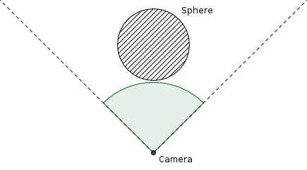
return (nearest_distance, nearest_sphere) Which always ensures that the nearest sphere (and its associated intersection distance) is always returned. If the ray does not actually intersect anything, you might choose to return a null sphere object, a negative distance, or set a boolean flag to false, this is all up to you and how you choose to implement the ray tracer, and will not make any difference as long as you are consistent in your design choices. We now have enough code to render this sphere! Let's add a sphere of radius 1 with its center at (0, 0, 3), that is, three units down the z-axis, and set our camera at the origin, looking straight at it, with a field of view of 90 degrees. Looking top-down, the world would look like this:
If we "render" this sphere by simply checking if each camera intersects something in the world, and assigning the color white to the corresponding pixel if it does and black if it doesn't, for instance, like this:
for each pixel (x, y) in image
{
  // calculate resolution-independent coordinates
  u = (width / height) * (2 * x / width - 1);
  v = (2 * y / height - 1);

  // obtain the corresponding camera ray
  camera_ray = GetCameraRay(u, v);

  // perform an intersection test
  has_intersection, sphere, distance = nearest_intersection(camera_ray);

  if has_intersection
    pixel = white;
  else
    pixel = black;
}
We would obtain something like this:
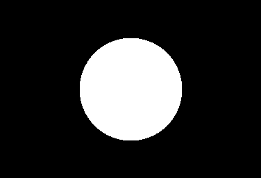
It looks like a circle, of course, because the projection of a sphere on a plane is a circle, and we don't have any shading yet to distinguish the sphere's surface. What we need is lighting.
Lighting
Lighting is a rather expansive topic. But we'll start simple, using point light sources, which are idealized light sources which occupy a single point in space and emit light in every direction equally (if you've worked with any graphics engine, there is probably a point light source emitter available). The goal of lighting is essentially to calculate the amount of light entering the camera for every pixel on the image, according to the geometry and light sources in the world.
In general, we can assume that light behaves as a beam, i.e. it has an origin and a direction like a ray, and travels in a straight line until interrupted by an obstacle, and has an infinitesimally small cross-sectional area.
Let's take our previous world, and let's add a point light source somewhere between us and the sphere. Then there are only two paths that a light ray emitted by the light source can take to reach the camera:
- the light ray leaves the light source and immediately hits the camera
- the light ray bounces off the sphere and then hits the camera
We'll ignore the first case for now: a point light source has no volume, so we cannot technically "see" it - it's an idealized light source which has no physical meaning, but is easy to implement. The second case is the interesting one. If we go back to our ray tracing code, we already know (for each pixel) the intersection point of the camera ray with the sphere, since we know the intersection distance. Therefore, we can calculate the path the light ray will have taken to reach the camera, as this diagram illustrates:
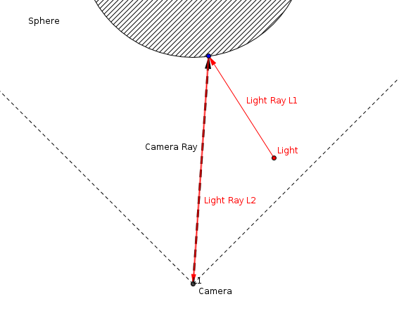
So all we really need to know to measure how much light reaches the camera through this path is:
- how much light is emitted by the light source along L1
- how much light actually reaches the intersection point
- how much light is reflected from that point along L2
We'll need answer each question in turn in order to calculate the lighting on the sphere. In effect, we are deriving the path light will take through our world.
How much light is emitted by the light source along L1?
This one is easy. Presumably the intensity of the light source would be an intrinsic property of the light, which can be configured, and a point light source emits equally in all directions.
We will not worry about physically based units and other advanced lighting details for now.
How much light actually reaches the intersection point?
Contrary to popular belief, the intensity of a light ray does not decrease inversely proportional to the square of the distance it travels (the famous inverse-square falloff law). Once a light ray is emitted, it travels with constant intensity (in real life, the light ray will gradually fade by being absorbed by the medium it is travelling in, but at a rate nowhere near the inverse square of distance). What people really want to convey when they say this is that the probability of a light ray emitted in a particular direction reaching you (or, more generally, some surface) decreases with the inverse square of the distance between you and the light source. Because light travels at a very high velocity, on average the amount of light received from the light source appears to be inversely proportional to the square of the distance.
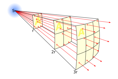
This may seem like a fairly trivial distinction, and basically is at this point, but will become of major relevance in later parts when we go on to formalize light transport in the language of probability and statistics. For now, just keep this in mind, and try to think in terms of probabilities ("what are the odds that") rather than in absolutes.
So, applying this inverse-square law to our problem, we see that the amount of light \(L\) reaching the intersection point is equal to: \[L = \frac{I}{r^2}\] Where \(I\) is the point light source's intensity (as seen in the previous question) and \(r\) is the distance between the light source and the intersection point, in other words, length(intersection point - light position).
How much light is reflected from that point along L2?
This question is interesting. Not all objects reflect light in the same way (for instance, a plastic surface and a mirror), so the question essentially amounts to "how does this object reflect light?". We haven't actually defined how we want our sphere to reflect light, so far we've just been thinking of it as a geometric object that light rays bounce off of. To get us going, we'll decide that our sphere will reflect light that bounces off of it in every direction, similar to most matte objects you can think of (dry wood, concrete, etc..).
In other words, when a light ray hits the surface of the sphere, it would "spawn" (conceptually) infinitely many other light rays, each going in different directions, with no preference for any particular direction. This is called diffuse lighting, and the way light reflects off an object depends on the object's material (just like the way light hits the object in the first place depends on the object's shape. So does that mean that the amount of light reflected towards the camera is equal to the amount of light that arrives? No, of course not. Otherwise, there wouldn't be any light left for the other directions.
Remember, light is a form of energy, and because of energy conservation, the amount of light that reflects at a point (in every direction) cannot exceed the amount of light that arrives at that point, otherwise we'd be creating energy. So does that mean the energy of that light ray is "spread out" over every possible direction, so that the intensity of the reflected light ray in any given direction is equal to the intensity of the arriving light source divided by the total area into which the light is reflected? That's correct.
We haven't really defined what that "total area" is however, and we'll do so now. Imagine looking at the moon on a full moon. It appears to occupy a certain area of your field of vision. You might not be able to measure it, but you can compare it with other objects that appear bigger or smaller. Now block out the moon with your thumb. It appears the same size as the moon to you, yet is infinitesimally smaller. We define the "solid angle" (units: steradians) of an object as the amount of space it occupies in your field of vision, assuming you were able to look in every direction around you, where an object occupying 100% of your field of vision (that is, it surrounds you completely) occupies a solid angle of \(4 \pi\) steradians, which is the area of the unit sphere.
In fact, the solid angle of an object is its area when projected on a sphere of radius 1 centered on you. That was a lot to take in, however it lets us continue: the total area into which light can be reflected is just the area of the unit hemisphere centered on the surface normal at the intersection point. This makes sense: light can't get reflected away from the normal, since that would mean it is going inside the sphere's surface. The area of the unit hemisphere is \(2 \pi\). So does that mean the reflected light is equal to \(\frac{1}{2 \pi} \frac{I}{r^2}\)? Not quite! There is one final phenomenon at play here, called Lambert's cosine law, which is ultimately a rather simple geometric fact, but one which is easy to ignore if you don't know about it. Consider the following diagram:
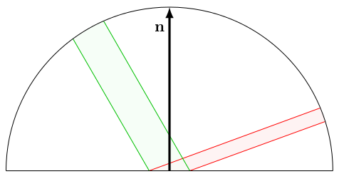
Here, the green beam of light arrives on a small surface area (\(\mathbf{n}\) is the surface normal). The same amount of light (energy) arrives no matter the angle of the green beam. The exact same amount of light is reflected via the red beam. However, and this is the crucial point, the area (in terms of solid angle) in which the red beam is emitted depends on the angle at which it is reflected. In fact, and this can be derived mathematically, that area is proportional to \(\cos{\theta}\) where \(\theta\) is the angle made by the red beam with the surface normal.
It is perhaps intuitive to think that the red light beam is "denser" than the green one, since the same amount of energy is packed across a smaller beam cross-section. This has significance, but we will need a deeper mathematical understanding of light before discussing it and will return to this further in the series.
So, in the context of our sphere and light source, this means that the intensity of the reflected light rays is going to be proportional to the cosine of the angle they make with the surface normal at the intersection point on the surface of the sphere. Because energy must be conserved, and due to the Lambertian cosine term, we can work out that the amount of light reflected towards the camera is equal to: \[L = \frac{1}{\pi} \cos{\theta} \frac{I}{r^2}\] What is this \(\frac{1}{\pi}\) factor doing here? It has to do with the fact that adding up all the reflected light beams according to the cosine term introduced above ends up reflecting a factor of \(\pi\) more light than is available. Therefore we have to divide by \(\pi\) to make sure energy is conserved. This is a common pattern in lighting equations and in the next part we will explain more in detail how we arrived at this derivation. For now, I think you will agree with me if I tell you we've done enough maths for now.
To the code!
Implementation
First of all, we're going to need to add some extra functionality to our sphere: we need to be able to calculate the surface normal at the intersection point. For spheres, this is particularly simple, as surface normals at any point are always in the same direction as the vector between the center of the sphere and that point (because it is, well, a sphere). So the normal calculation consists of getting the vector between the sphere's center and the point, and dividing it by the sphere's radius to get it to unit length:
Vector GetNormal(Point p)
{
  return (p - sphere.center) / sphere.radius;
}
Normalizing the vector would work just as well, but since the point is on the surface of the sphere, it is always one radius away from the sphere's center, and normalizing a vector is a rather expensive operation compared to a division.
So, if we implement all the theory, we get this:
for each pixel (x, y) in image
{
  u = (width / height) * (2 * x / width - 1);
  v = (2 * y / height - 1);

  camera_ray = GetCameraRay(u, v);
  has_intersection, sphere, distance = nearest_intersection(camera_ray);

  if has_intersection
  {
    intersection_point = camera_ray.origin + distance * camera_ray.direction;
    surface_normal = sphere.GetNormal(intersection_point);
    vector_to_light = light.position - intersection_point;
    cosine_term = dot(normalize(vector_to_light), surface_normal);

    // dot(u,v) = |u| |v| cos(theta)
    // and both vectors are unit length
    // make sure the cosine term is positive (can't have negative amounts of light!)
    if (cosine_term < 0)
      cosine_term = 0;

    reflected_light = (1 / pi) * cosine_term * light.intensity / length(vector_to_light)^2;
    pixel = reflected_light;
  }
  else
    pixel = black;
}
We get something like this (depending on where you placed your sphere and light source):
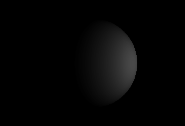
Which looks pretty good.
RGB color channels are completely independent for a physics point of view. Therefore you can treat each channel as having its own intensity, which lets you give colors to light sources. In the pseudocode above, the light is therefore white, as it emits the same intensity for each channel. Objects can also reflect light of different color in different ways, here the sphere doesn't care and just reflects the same way for all three channels. To give color to individual spheres, you can make them reflect red, green, and blue in various amounts.
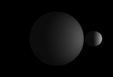
We note that the side of the sphere opposite the light source is completely black, since it receives no light at all. We can add an ambient lighting term so we can make out the outline of the sphere anyway. Furthermore, if you want to handle multiple lights, there's no problem: do the lighting calculation on every light, and add up the results, as you would expect. However, you might notice that the result we obtained doesn't look too different to what you can get with a trivial OpenGL/DirectX shader, yet is a hell of a lot more work. That's because we haven't actually made use of any of the features of ray tracing, and we're about to begin doing that right now. What if there was a small sphere in between the light source and the bigger sphere? With the current code we'd get this:
This isn't right - light doesn't just magically travel through the smaller sphere. That's because we haven't accounted for whether the light ray between the intersection point and the light source is actually clear of obstacles. If it isn't, obviously no light can travel along it. This can be fixed easily enough by adding an occlusion testing function which checks if there is an intersection along a ray from the origin of the ray up to a certain distance (e.g. we don't care if there is an obstacle beyond the light source). This function can be implemented easily by again checking if the intersection distance for every sphere is smaller than the distance to the light source, but one difference is that we don't need to keep track of the closest one, any intersection will do.
You can technically implement the occlusion testing function via the nearest intersection function developed earlier, but it is not very efficient since you don't need to do all the work the latter does when just checking for any obstacle along the ray. However, for now, it probably does not matter much.
Now that we have this occlusion testing function, we can just add a little check before making the light source contribute to the lighting:
for each pixel (x, y) in image
{
  u = (width / height) * (2 * x / width - 1);
  v = (2 * y / height - 1);
  camera_ray = GetCameraRay(u, v);
  has_intersection, sphere, distance = nearest_intersection(camera_ray);

  if has_intersection
  {
    intersection_point = camera_ray.origin + distance * camera_ray.direction;
    surface_normal = sphere.GetNormal(intersection_point);
    vector_to_light = light.position - intersection_point;
    distance_to_light = length(vector_to_light);
    ray_to_light = new Ray(intersection_point, normalize(vector_to_light));

    // is there an obstacle between intersection_point and light.position?
    if not occluded(ray_to_light, distance_to_light)
    {
      cosine_term = dot(normalize(vector_to_light), surface_normal);
      if (cosine_term < 0) cosine_term = 0;
      reflected_light = (1 / pi) * cosine_term * light.intensity / distance_to_light^2;
      pixel = reflected_light (+ ambient color);
    }
    else
      pixel = black (+ ambient color);
    // light source occluded
  }
  else
    pixel = black;
}
And the result:
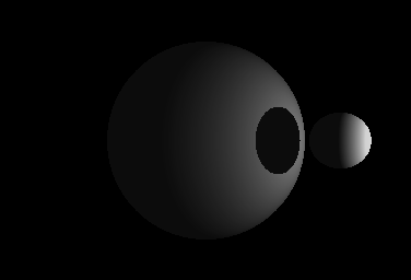
Perfect. How easy was that? Lots of physical effects that are a pain to add in conventional shader languages tend to just fall out of the ray tracing algorithm and happen automatically and naturally. This is one of the main strengths of ray tracing.
When you try to implement this yourself you might notice some curious artifacts with the lighting. The problem is when calculating the intersection point's position - due to floating point inaccuracy, it is possible that this point ends up landing inside the sphere, which screws up the subsequent occlusion test. This is a widespread problem in ray tracing algorithms, called self-intersection, which cannot really be cured in a general way without fixed point arithmetic. The typical workaround is to nudge the intersection point outside the sphere by pushing it along the surface normal very slightly.
What's Next?
So far, our ray tracer only supports diffuse lighting, point light sources, spheres, and can handle shadows. Technically, it could handle any geometry, but we've only implemented the sphere so far. In the next article, we will begin describing and implementing different materials. We will also introduce the field of radiometry and see how it can help us understand the physics of light reflection, and we will clear up most of the math in this section, some of which was admittedly handwavy. We will also start separating geometry from the linear transforms (such as translation, scaling, and rotation) that can be done on them, which will let us implement geometry instancing rather easily. We'll also implement triangles so that we can build some models more interesting than spheres, and quickly go over the theory of anti-aliasing to make our renders look a bit prettier. The next article will be rather math-heavy with some calculus, as it will constitute the mathematical foundation of all the subsequent articles.
References & Further Reading
- http://en.wikipedia.org/wiki/Ray_tracing_(graphics)
- http://www.scratchapixel.com/lessons/3d-basic-lessons/lesson-7-intersecting-simple-shapes/ray-sphere-intersection/
- http://mathworld.wolfram.com/Projection.html
- http://en.wikipedia.org/wiki/Lambert's_cosine_law
- http://en.wikipedia.org/wiki/Diffuse_reflection


This is something I've been meaning to learn for the longest time. Thanks for taking the time to write this in depth guide. I'm looking forward to the next article in the series.