Vehicle physics pacejka lateral velocity

Started by
21 comments, last by YousefMahmood 1 year, 9 months ago

Recently i started looking into vehicle physics/simulations and tire friction models.I've looked into the pacejka tire friction model and attempted to apply in a physics engine (bullet physics in this case) in which the chassis is a dynamic rigidbody while the wheels are implemented via a raycast suspension system.My main two references are the car physics article by "Macro Monster"

https://asawicki.info/Mirror/Car%20Physics%20for%20Games/Car%20Physics%20for%20Games.html​

and this thesis/master project about car physics for games:

https://nccastaff.bournemouth.ac.uk/jmacey/MastersProject/MSc12/Srisuchat/Thesis.pdf

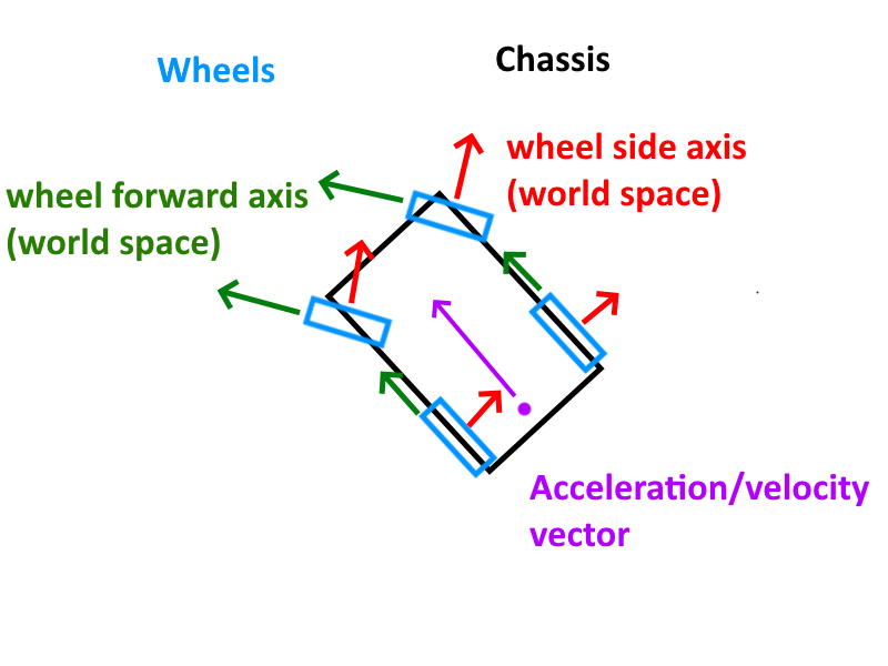
Here is a simple mockup of how my vehicle setup looks like in the engine: (from the top down perspective):

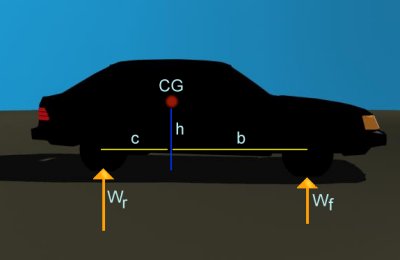
To keep things simple the acceleration/force is applied at the center of the rear axle in the direction of the cars local forward axis. Friction is applied to each wheel seperately. (I know that this setup isn't physically accurate but i wanted to keep things simple for now.) Forces are also applied on the same height level as the center of mass so the car doesn't start to roll in curves. (Weight transfer is in general ignored here. Weight is essentially equally distributed over all wheels/suspensions.) Front wheel ackermann steering is also implemented.

So to implement the lateral friction/cornering force i used the normalized pacejka formula which i took from this wikipedia article: https://en.wikipedia.org/wiki/Hans_B._Pacejka

static float pacejka(float slipAngleDegrees){
	float x = slipAngleDegrees;
	float B = 0.714;
	float C = 1.40;
	float D = 1.00;
	float E = -0.20;

	return D * sin(C * atan(B * x - E * (B * x - atan(B * x))));
}

From my understanding the pacejka formula requires the input parameter (slip angle) to be in degrees and NOT radians. (Although from cross referencing pacejka implementations over the net i've sometimes seen radians used as well. So i'm not entirely sure if that's accurate.)

So now we want to calculate the lateral velocity for each wheel and apply the pacejka formula to it.

In bullet physics rigibodies have a getVelocityInLocalPoint(position) function to return the velocity of a rigidbody in a given point.

Here kind of a pseudocode how the calculation looks like (very simplified): Note that in the example mentioned above i don't apply the force directly at the raycast contactpoint with the ground to avoid body roll. (The pseudocode does that to get the idea along.)

int wheelCount = 4;
for each wheel w{ //we have 4 wheels
	vec3 tireVelocity = rigidbody->getVelocityInLocalPoint(w.localContactPoint); //w.localContactPoint is where the suspensionraycast hits the floor relative to the rigidbody origin)
	float lateralVelocity = dot(tireVelocity,w.sideAxis); //sideAxis is the red normal in the image shown above which is the wheels side axis in world-space
	float longitudinalVelocity = dot(tireVelocity,w.forwardAxis); //green normal in above image
 	
	//calculate slip angle
	float slipAngleRadians = std::atan2(lateralVel,longitudinalVel);//slipangle in radians
 	
	//pacejka requires slipangle to be in degrees.
	float slipAngleDegrees = slipAngleRadians * 180.0f/PI;
 	
	float pacejkaValue = pacejka(slipAngleDegrees);

	float tireLoad = chassisMass * gripValue; //simplification. gripValue = 30.0f; (example)
	 	
	//calculate lateral force. tireLoad * pacejkaValue / wheelCount
	float lateralForce = (tireLoad * pacejkaValue) / float(wheelCount);
 	
	//apply lateral force along the wheelsideaxis at its contact point
	rigidbody.applyForce(-w.sideAxis * lateralForce,w.localContactPoint);
 
}

The issue with that implementation is that in curves the car starts oscillating between the current angular velocity and the direction of travel. That's how it looks like in-engine:

Now of course i know that this implementation is a very crude simplification of the tire friction model (as other aspects as weight transfer are ignored) but i'm not sure if the way lateral forces are calculated is correct.

The oscillations you see (the car bobbing left and right after taking a turn until it starts to rest) also happen at lower speeds but it gets more pronounced at higher ones. You can see those oscillations also occur in the graphs on the left side of the screen (lateral pacejka values and lateralforce changes due to the car constantly vibrating left and right) You can even see how the car rapidly spins out at the end which looks completely unnatural. (so maybe my entire approach is wrong.)

My suspicion is/was that the center part of the pacejka formula (where the lateralVelocity gets near zero) the force applied to the wheel also rapidly decreased (marked in red):

Which in theory might work, the issue however is that (at least from my understanding) the car should essentially have full grip capabilities at those narrow slip angles. But because the lateral forces rapidly decrease at those narrow slip angles the still doesn't have entirely full grip in this range (it rapidly gets there but essentially the car still slides to a small degree) which i think is what causes those oscillations to occur.

My initial thought was that the pacejka formula should look somewhat like this (red line):

Where the force on the small slip angles is still high enough to “rotate” the car towards its resting position by basically applying enough force to immediately setting its angular velocity the the intended one during a full grip situation (which happens anyway during low speed situations where pacejka cannot be applied.) . But now thinking about it this might not be entirely possible on a fully physics driven system.

Can someone shine more light into this? Is this behaviour shown in the video expected with the current implementation? Or am i overlooking a crucial detail somewhere? (Maybe the slipangle calculation should remain in radians and not degrees?) Woould appreciate any kind of tips/guides into the correct direction.

Advertisement

Which in theory might work, the issue however is that (at least from my understanding) the car should essentially have full grip capabilities at those narrow slip angles. But because the lateral forces rapidly decrease at those narrow slip angles the still doesn't have entirely full grip in this range (it rapidly gets there but essentially the car still slides to a small degree) which i think is what causes those oscillations to occur.

My initial thought was that the pacejka formula should look somewhat like this (red line):

<snipped image of graph>

The Pacejka formula is modeling full grip capabilities at narrow slip angles, even though the force diminishes as the slip angle approaches zero. Remember that the Pacejka model is an empirical model that's built to fit measured data. In the real world, when a tire experiences a narrow slip angle, a certain portion of the contact patch (which has area, and is not just a single infinitely small point) will adhere to the road 100%. Because of that adherence, the tire will deform and that deformation will essentially attempt to “pull” the wheel back in line with the contact patch. This force, of the tire resisting deformation caused by the contact patch adhering to the road, is what contributes the lateral force at slow slip angles.

As the slip angle increases, the amount of deformation increases and the force of the tire resisting that deformation similarly increases. This is the linear part of the Pacejka curve, the part in your graph that goes from 0 degrees to roughly 2 degrees. The slope of that line is frequently referred to as the “stiffness" of the tire response, and we can think of a steeper slope as being a stiffer tire (ie a tire that more strongly resists deformation).

As the slip angle increases further, we hit a peak where the contact patch can no longer fully adhere to the road. Parts of the contact patch will begin to slip (perhaps starting at the back of the patch where there is less pressure pushing between the tire and the ground). Consequently, the lateral force plateaus and, as the slip angle increases further still and more of the contact patch slips, begins the decrease. This is the justification for the general shape of the Pacejka curve: it starts at 0, increases up to a peak (where the patch begins to slide) and then decreases down to a lower level where the entire contact patch is sliding.

So, the curve that you have is correct. Now, because this is an empirical model, it's important to have good values for B, C, D and E. This can be tricky without actual tire data and requires a bit of fiddling to get something that feels right. Your values look fine, though, so I wouldn't worry about that too much just yet.

As for the oscillations:

I am not entirely sure what's causing that, and it may just require more debugging. [EDIT: I deleted an incorrect bit that suggested the slip angle calculation was wrong. I had spaced out and was thinking of the calculation of slip ratio instead]

As for radians vs degrees:

Not important. The Pacejka formula just gives a format to create the general shape of the force curve. If you want to input slipAngle in degrees, your B, C, D, and E constants will merely have to be set in such a way that you get a proper curve with a peak at the desired slipAngle (in degrees). If you later decide to do your math with radians, you'll need to adjust your constants to get the curve in the correct shape for your new radian inputs.

Samith said:

As for the oscillations:

I am not entirely sure what's causing that, and it may just require more debugging. I will however point out that your slip angle calculation is using the velocity of the wheel and not the velocity of the contact patch, which is slightly different. This code below adjusts the longitudinalVelocity to reflect the velocity of the contact patch by subtracting the angularVelocity * radius of the tire.

vec3 tireVelocity = rigidbody->getVelocityInLocalPoint(w.localContactPoint); //w.localContactPoint is where the suspensionraycast hits the floor relative to the rigidbody origin)
float lateralVelocity = dot(tireVelocity,w.sideAxis); //sideAxis is the red normal in the image shown above which is the wheels side axis in world-space
float longitudinalVelocity = dot(tireVelocity,w.forwardAxis) - tireAngularVelocity * tireRadius; //green normal in above image

Ah so i assume that due to the reduction of dot(tireVelocity,w.forwardAxis) by the angular velocity causes the slipAngle to increase which in turn causes a greater cornering force. And with that assumption, not doing the subtraction (which would be equivalent to having full breaks enabled on the tires causing an angular velocity of 0) would be equivalent of a lateral force during full breaks enabled right? (which in turn can causes the car to slip more on the surface.)

I assume that the tireangularVelocity is defined in radians/s correct? (and by multiplying it with the radius we get the distance the tire travels?)

Would you mind pointing me into the correct direction when it comes to the subtraction of the angular velocity and/or where i can read up on this more?

I've cross referenced multiple articles as well as tire model implementations on the internet (with pacejka) i could find and haven't seen the reduction by the tireangularVelocity just yet. (Unless it was indirectly done by other means which i've overlooked in the more complex implementations.)
The article as well as thesis mentioned above calculates the slip angles like this:

whereas “wb” and “wc” is the driveshaft distance from the center of gravity to the front axle and reat axle. (if i understood that correctly.)

for vlong they specify:

vlong is car speed a.k.a. longtitudinal velocity (in m/s)

Where the tire angular velocity isn't mentioned hence my assumption of simply doing dot(tireVelocity,w.forwardAxis). (So no subtraction) Although one thing i noticed is that this seems to use the lateral velocity of the car/chassis and not from the wheel. (Which can be different for the front wheels due to their steering rotation.)

They calculate a sigma value which they then subtract from the slipangle from the front wheels:

I think that this is because they manually calculate the angular torgue of the cars body along the center of mass due to the steering (and they have to calculate this force manually) which i think is not nessecary in the case of physics engines like physX or bullet as bullet already applies the correct angular torgue to the body depending on the force vector and the position where its applied on the body via rigidbody.applyForce(force,position);.)

Samith said:
As for radians vs degrees: Not important. The Pacejka formula just gives a format to create the general shape of the force curve. If you want to input slipAngle in degrees, your B, C, D, and E constants will merely have to be set in such a way that you get a proper curve with a peak at the desired slipAngle (in degrees). If you later decide to do your math with radians, you'll need to adjust your constants to get the curve in the correct shape for your new radian inputs.

Makes sense. My assumption came from having seen the ABCD factor to be labeled as “shapefactor, stiffnesfactor,latCurveFactor”, etc… so i thought that their unit would be standardised across pacejka implementations (either for degrees or radians as an input.) Guess thats not the case then.

/Edit:

Adding proper weight transfer on the suspension somewhat fixes this issue. (So the oscillation might be a natural sideffect if all tires have the exact same load. With varying differences due to tire load this dampens itself out rather quickly.)

My apologies, you are correct re: the slip angle. I was thinking of the slip ratio. I'll edit my response so that future readers don't get confused!

My theory regarding your oscillations is that something like this is happening:

  • You steer the wheel, going from 0 to 10 degrees of steering angle on the front tires
  • This naturally introduces a slip angle on the front tires, which causes a lateral force at the front which begins to rotate the car
  • As the car rotates, the back starts to get a slip angle as well, so now you have lateral force on the front and rear
  • Due to this lateral force on front and rear, the lateral velocity of the car begins to slow as it approaches its new heading
  • Since the lateral velocity is decreasing, the slip angle on the back begins to decrease, but not on the front, due to the continued 10 degree steering angle
  • Once the lateral velocity has slowed enough, you end up with very little slip angle in the rear, and thus little lateral force in the rear
  • But you still have lateral force in the front, and as such the car begins to rotate again, introducing a new slip angle in the rear!
  • The process repeats itself a few times until the car settles

So, I don't think you've incorrectly implemented the lateral force equations. You're just seeing the natural complexity of this system. You might be able to mitigate the effect somewhat by decreasing the stiffness of the tire friction curve, ie making the peak lateral force occur at a larger slip angle than the current ~3 degree peak. Other things that can affect this are the “wc” and “wb” values you referenced above. A larger wb relative to wc will cause the torque from the lateral force of the front wheels to be higher than the torque from the rear wheels, which might make it harder for the car to balance out in these big steering maneuvers.

Beyond that I don't really have any specific solution! [EDIT: And even the above suggestions are just guesses! Even a simple car model can be complicated and hard to predict how the behavior will change with any given modification] In implementing my own vehicle sim I came across a lot of oscillations and weird dynamic effects. A car in the real world has lots of oscillations and weird dynamic effects as well ? The solution for me usually required tweaking values and finding a nice balance to make things work out.

I can't help you with the theory of it, as I am still noob at physics engine programming, but I don't know if you have heard about Offroad game engine, there are a few videos on youtube of this game engine with custom car physics (using pacejka tyre model) and the source code is available at https://sourceforge.net/projects/offroad/​ if you want to search through and check the diffs with your own code.

Hello,

I just quickly read through this thread and may have a couple of ideas:The Marco Monster's car physics is one of my favorite, but it deals with a sort of 2D car (bicycle). It can mislead you when making real 3D physics. Weight transfer is one thing that's quite important, but you don't have to calculate it directly. It “comes” automatically when you have a proper suspension and/or tire simulation. Simply said, you can get the tire load from the compression of the suspension.

I'd also suggest reading Brian Beckman's Physics of Racing. You already have the base knowledge so the imperial units used in that paper will not confuse you. Also it discusses the Magic Formula in more depth, also has a fairly good approach to combine longitudinal and lateral forces.

Speaking of Pacejka, you'll do yourself a favor by forgetting the normalized formula from Wikipedia that only uses BCDE and an input slip. One point you'll need load sensitivity and camber. The full fledged MF89/94/96 (the old ones) have much more parameters to play with, also they have more inputs: Slip / Load / Camber

Make sure you are calculating / applying forces in the right coordinate frame. All tire calculations are local to the tire-space, but before applying those on the rigid body you must transform them back to vehicle-space. If you do so, both front and rear wheels will behave the same way, no matter which one has steering input.

What is the frequency of your simulation? General physics engines run at 60Hz. Most popular sims (including mine, which is not popular ?) run at 1000Hz. This can cause oscillations too. The tire and spring simulation can be quite unstable, which is “mitigated” by the high frequency. Sport or racing suspension is nearly impossible to achieve with 60fps physics.

You don't have to worry about low speed problems yet, but be prepared ?

Here are a couple of goodies:

http://ceb.ac.in/knowledge-center/E-BOOKS/Physics%20Of%20Racing%20Series%20-%20Brian%20Beckman.pdf

https://www.edy.es/dev/docs/pacejka-94-parameters-explained-a-comprehensive-guide

http://racer.nl

jackw1111 said:

I can't help you with the theory of it, as I am still noob at physics engine programming, but I don't know if you have heard about Offroad game engine, there are a few videos on youtube of this game engine with custom car physics (using pacejka tyre model) and the source code is available at https://sourceforge.net/projects/offroad/​ if you want to search through and check the diffs with your own code.

Will check that out. ?

bmarci said:
I just quickly read through this thread and may have a couple of ideas:The Marco Monster's car physics is one of my favorite, but it deals with a sort of 2D car (bicycle). It can mislead you when making real 3D physics. Weight transfer is one thing that's quite important, but you don't have to calculate it directly. It “comes” automatically when you have a proper suspension and/or tire simulation. Simply said, you can get the tire load from the compression of the suspension.

I noticed. Have found forks/ports of Macro Monsters implementation on the web (the original code is down/unavailable) and they seem to be based on 2D.

bmarci said:
I'd also suggest reading Brian Beckman's Physics of Racing. You already have the base knowledge so the imperial units used in that paper will not confuse you. Also it discusses the Magic Formula in more depth, also has a fairly good approach to combine longitudinal and lateral forces.

Will do so. From research/experimentation i found out that in order to implement proper drifting (where tire spin causes the loss of lateral friction) a combined forces approach (friction circle) is needed. (Which was confusing at first as a lot of articles/implementations calculate those forces seperately and then simply add the lateral and longitudinal pacejka vectors together. But this doesn't reflect expected tire behaviour at all.)

bmarci said:
Speaking of Pacejka, you'll do yourself a favor by forgetting the normalized formula from Wikipedia that only uses BCDE and an input slip. One point you'll need load sensitivity and camber. The full fledged MF89/94/96 (the old ones) have much more parameters to play with, also they have more inputs: Slip / Load / Camber

Will also look into that in the long run. But i wanted to make sure that even with the simplified formula i get something that at least resembles somewhat correct tire behaviour. (which is not the case right now.)

bmarci said:
ake sure you are calculating / applying forces in the right coordinate frame. All tire calculations are local to the tire-space, but before applying those on the rigid body you must transform them back to vehicle-space. If you do so, both front and rear wheels will behave the same way, no matter which one has steering input.

That should already be the case. All tire calculations are in tire space and then get applied/transformed to vehicle space.

bmarci said:
What is the frequency of your simulation? General physics engines run at 60Hz. Most popular sims (including mine, which is not popular ?) run at 1000Hz. This can cause oscillations too. The tire and spring simulation can be quite unstable, which is “mitigated” by the high frequency. Sport or racing suspension is nearly impossible to achieve with 60fps physics.

You don't have to worry about low speed problems yet, but be prepared ?

i run this at 250hz. But i also tried 500hz. Tire load should be correctly calculated AFAIK. As you said i simply use the suspension for that.

According to this site: https://www.engineeringtoolbox.com/tractive-effort-d_1783.html​ the traction force is equals to

tractionForce = mass * gravity * tractionCoefficient

So for a 2000kg car with the gravity of 9.81m/s we get

2000 * 9.81 = 19620N

divide by 4 as the load is spread to all wheels (on avg) > 19620/4 = 4905N per wheel (tireLoad)

and then i calculate the longitudinal velocity for example like this:

Game::VehiclePhysics::PacejkaData pacejkaLong;
pacejkaLong.B = 10.0;//Stiffness
pacejkaLong.C = 1.9;//Shape
pacejkaLong.D = 1.00;//Peak
pacejkaLong.E = 0.97;//Curve

wheelInfo.slipRatio = ((wheelInfo.angularVelocity * wheelInfo.tireRadius) - longitudinalVelocity) / std::max(std::abs(longitudinalVelocity), 0.00001f);
wheelInfo.longitudinalTractionForce = Game::VehiclePhysics::pacejka(wheelInfo.slipRatio, pacejkaLong) * wheelInfo.tireLoad * tractionCoefficient;

Tractioncoefficient is 0.9 for dry asphalt. Although in the longitudinal example you get instability at near 0 speed.

My main issues right now are that even with the normalised pacejka formula and tireload (which should behave correctly with weight transfer) the car still tends to slide like on ice on moderate to higher speeds. (I suspected that the tireload is wrong/too low even though the calculations should check out. Maybe i'm overlooking a factor somewhere which would increase the tires grip.)

The grip issue also can be seen during acceleration where the cars tires spin constantly (at even lower speeds) but the friction doesn't have enough strength to push the body forward as expected.

In the video you can also see that the friction forces cause the tire to oscillate/spin eradically (due to the instability of the slipratio near 0. But there also seems to be something wrong with the friction force altogether due to its slidy behaviour.). As if the tire/angular velocity is too overly sensitive to the tractionForce & enginetorque but the tractionForce itself is way too low too actually push the car forward. (At least it feels like it.)

On the right side of the screen you can see the longitudinal/lateral vector of the traction in the wheels local space. Front left, front right, bottom left and bottom right which is outside of the screen.

Lewa said:
Will do so. From research/experimentation i found out that in order to implement proper drifting (where tire spin causes the loss of lateral friction) a combined forces approach (friction circle) is needed. (Which was confusing at first as a lot of articles/implementations calculate those forces seperately and then simply add the lateral and longitudinal pacejka vectors together. But this doesn't reflect expected tire behaviour at all.)

Adding them is simply wrong, just imagine locking the front wheel and you are still able to steer. So you must cut back the lateral force when longitudinal is exceeding the limit. Newer formulas MF6.1 for example deals with combined behaviour, but much more difficult to find the decent parameters, probably that's why most of us stuck with the old pacejka, there are Sh*t load of parameters you can find out there ?

The drifting is not easy ? It's not only up to the tire spin, but suspension setup and differentials, and not to mention driving technique and skills.

Lewa said:
wheelInfo.slipRatio = ((wheelInfo.angularVelocity * wheelInfo.tireRadius) - longitudinalVelocity) / std::max(std::abs(longitudinalVelocity), 0.00001f);

I suppose the longitudinalVelocity is the velocity of the car at the position of the tire, and transformed into wheel-space and only taking the longitudinal component of the velocity vector ?

Looking at the video, the slip/force values seem good.

The low speed instability should completely vanish above 5-10m/s

Is your rpm in rad/s?

This topic is closed to new replies.

Advertisement